Programming method using STL instructions
First, the STL / RET instruction
The STL instruction allows the programmer to generate procedures and procedures that work very close to the sequential function diagram.
The meaning of the STL instruction is to activate a step (ie state), which is represented on the ladder diagram as a state contact drawn from the main bus. The STL instruction has the function of creating a sub-bus, so that all operations in this state are performed on the sub-bus.
Step Return Instruction RET is the end of the status flow and is used to return to the main bus.
In general, the FX series plc uses the stater S to program the sequence program and use it with the STL instruction.
1. Conversion between sequential function diagram and step ladder diagram
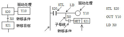
The step function diagram can be converted to a step ladder using the step ladder command STL and the step return command RET. The corresponding relationship is shown in the figure below.

The circuit block driven by the ST L contact has 3 functions:
1, the driver processing of the load, that is, what to do in this step;
2. Specify the transfer condition, that is, if the condition is met, the step is exited;
3. Specify the transfer target, that is, what is the next state.
2. Step ladder programming rules
(1) The initial step can be driven by other steps, but the operation must start with other methods in advance, otherwise the state flow cannot be performed downward.
(2) The step ladder programming sequence is: first drive, then transfer. The order of the two cannot be reversed.
(3) The STL instruction must be used to program the steps on each sequential function chart.
(4) The drive circuits of the STL contacts are generally put together. When the last STL circuit ends, the step return instruction RET must be used to return to the main bus.
(5) STL contacts can be driven directly or through other contacts, such as Y, M, S, T, C and other components of the coil and application instructions.
(6) The drive load uses the OUT command. When the same load requires continuous multi-step drive, multiple outputs can be used. The load can also be set using the SET instruction. When the load does not need to be driven, it can be reset by the RST instruction.
(7) Since the CPU only executes the circuit blocks corresponding to the active step, the “double coil” output is allowed when the STL instruction is used, that is, different STL contacts can respectively drive one coil of the same programming element.
(8) The contact connected to the STL contact uses the LD or LDI instruction.
(9) During the transition of the active state of the step, the state controllers of the two adjacent steps will simultaneously ON for one scan period, which may cause an instantaneous double coil problem. In order to avoid the simultaneous operation of the two outputs that cannot be turned on at the same time (the contactor coil that controls the motor’s forward and reverse rotation as shown in the figure below), in addition to setting the software interlock circuit in the ladder diagram, the normally closed touch should be set outside the PLC. A hardware interlock circuit composed of points.
10) Both the SET command and the OUT command can be used to transfer the active state of the step. The state device corresponding to the original active step can be reset, and the subsequent step can be set as the active step. In addition, there is a self-holding function.
(11) The number of branches at a branch in a parallel sequence and a selection sequence cannot exceed 8.
(12) The ANB, ORB, MPS, MRD, and MPP instructions cannot be used in the circuit corresponding to the transition condition.
Second, single sequence programming
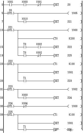
At the beginning of the feeding trolley, stop at the right limit switch X1 as shown below. Press the start button X3, Y2 is ON, open the gate of the hopper, start loading, and the timer T0 is timed. After 8s, the gate of the hopper is closed, Y2 becomes OFF, Y1 turns ON, and the left line starts. When the limit switch X2 is touched, it stops and unloads, Y1 turns OFF, Y3 turns ON, and timer T1 starts timing. After 10s, Y3 turns OFF, Y0 turns ON, and the right line starts. When it touches the limit switch X1, it returns to the initial state. At this time, Y0 turns OFF and the car stops running.

According to the process requirements of the transport trolley, this is a sequential flow control process. The steps for designing the sequential function diagram are as follows:
(1) The entire work process is decomposed according to the process, and each process corresponds to one step (ie, state), and the steps are assigned as follows.
Initial state: S0.
Loading: S20.
Left line: S21.
Unloading: S22.
Right line: S23.
As can be seen from the decomposition of the above work process, the control system has a total of five steps.
(2) corresponds to the action of each step.
S0: No action.
S20: Drive Y2 is ON, the cart is loaded, and the timer T0 is started at the same time for 8s.
S21: Drive Y1 is ON, and the car starts to the left.
S22: Drive Y3 is ON, the trolley is unloaded, and the timer T1 is started at the same time for 10s.
S23: Drive Y0 is ON, and the car is on the right.
(3) Find out the transfer conditions for each step.
As can be seen from the work process, the transfer conditions for each step are:
S0: At the beginning of PLC power-on, it is set to ON by the initialization pulse M8002 (closed only one scan cycle), in preparation for the transfer of the active step. During the working process, it is set to ON by the right limit.
S20: The trolley is at the right limit X1 and press the start button X3, ie .
S21 : Normally open contact of T0.
S22: Left limit X2.
S23 : Normally open contact of T1.
After the above three steps, the sequential function diagram of the trolley control system is shown in the figure below. The following figures (b) and (c) are the corresponding ladder diagrams and instruction tables.


Third, select the sequence programming
Selecting a single branch from multiple branch processes is called a selective branch.
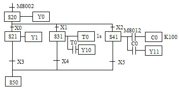
The transition between the sequential function diagram of the selection sequence and the step ladder diagram is shown in the following figures (a), (b) and (c).


The following figure shows a schematic diagram of a device that uses a conveyor belt to sort and transmit large and small balls. The sequence of actions is descending, sucking the workpiece, ascending, right shifting, descending, releasing the workpiece, ascending, and shifting to the left. The upper left is the origin. When the arm is lowered and the electromagnet is sucking the big ball, the limit switch SQ2 is turned off, and when the ball is sucked, the SQ2 is turned on to judge the big ball or the small ball.
The left shift and the right shift are controlled by Y4 and Y3 respectively. The rise and fall are controlled by Y2 and Y0 respectively, and the workpiece is sucked and controlled by Y1. When the arm moves to the upper limit, the left limit and releases, it is the origin position, that is, Y5 is the origin indication.
Upper limit: SQ3 ― X3
Lower limit: SQ2 – X2
Left limit: SQ1 ― X1
Right shift ball limit: SQ4 ― X4
Move the ball to the right to limit: SQ5 ― X5

According to the process requirements, the control flow can be divided into two branches according to the state of SQ2 (ie corresponding to the big and small balls), as shown in the following figure.