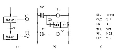
When programming with a stepping instruction, first design the state transition diagram and then convert it into a step ladder or instruction list according to the state transition diagram.
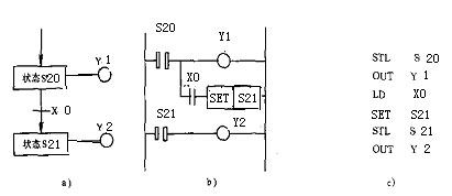
The action process is when the step contact S20 is closed, the output relay Y1 coil is turned on. When the X0 closed new state is set (turned on), the step contact S21 is also closed. At this time, the original step contact S20 is automatically reset (opened), which is equivalent to shifting the state of S20 to S21, which is the step conversion effect. State transition process between other state relays, and so on
It can be seen that the state transition diagram is a graph for describing the control process of the sequential control system, which consists of steps, transition conditions, and directed lines. Each state (step) represents an operation that works in sequence and requires a specific action to be completed. The transition (step) of the state is satisfied. Compared with ordinary instruction programming, the use of stepping instructions not only can intuitively represent the flow of sequential operations, but also can reduce the number of instructions and is easy to understand. Each state provides three functions: driving the load, specifying the transition condition, and setting the new state (while the transfer source is automatically reset).
There are four structures for state transition diagrams based on step and step progress:
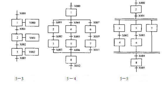
1. Single sequence. This basic progress is reflected in the sequential activation of the steps, as shown in Figure 5-3.
2. Select the sequence. An active step is followed by several subsequent steps to select the structural form as a sample sequence. As shown in Figure 5-4, each branch of the selection sequence has its own transition condition.
3. Parallel sequence. Parallel sequences are employed when the implementation of the conversion causes several branches to be activated simultaneously. The horizontal portion of the connected line is indicated by a double line. As shown in Figure 5-5.
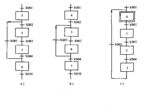
4. Step repeat and loop sequence. Jumping, repeating, and cyclic sequences are often used in practical systems. This sequence is actually a special form of the selection sequence.
As shown in Figure a, the skip sequence, when step 3 is the active step, if the transition condition X005 is established, skip step 4 and step 5 and directly enter step 6; b is a repeating sequence, and step 6 is the active step. If the conversion condition X004 is not established and X005 is established, return to step 5, and repeat steps 5 and 6 until the conversion condition X004 is established, and proceed to step 7; C is a cyclic sequence, and after the sequence is finished, repeat In this way, it returns directly to the initial step 0, forming a loop of the sequence.


